Hello readers, I’m no longer posting new content on gafferongames.com
Please check out my new blog at mas-bandwidth.com!
Introduction
Hi, I’m Glenn Fiedler. Welcome to Virtual Go, my project to create a physically accurate computer simulation of a Go board and stones.
In this article we want to draw the go stone using OpenGL.
Unfortunately we can’t just tell the graphics card, “Hey! Please draw the intersection of two spheres with radius r and d apart with a bevel torus r1 and r2!”, because modern 3D graphics cards work by drawing triangles. We have to take our mathematical definition of the go stone and turn it into a set of triangles that the graphics card can render.
This is called tessellation and there are several different ways to do it.
Longitude And Lattitude
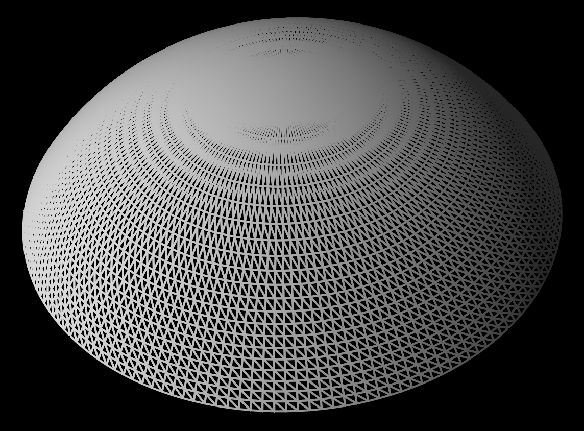
The first way that I tried was to consider sphere rendering like a globe with longitude/latitude. I started with a ring around the ’equator’ of the go stone, stepping these rings up to the top of the sphere like the north pole on a globe.
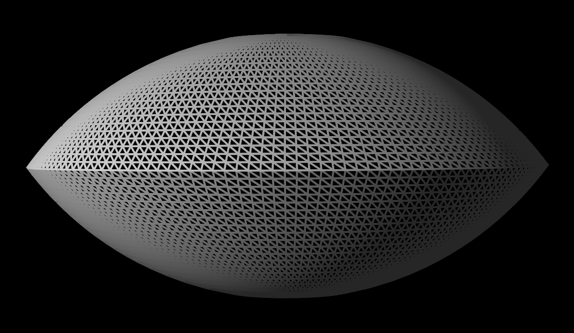
Unfortunately, just like longitude/latitude on a globe, tessellating this way leads to very distorted mapping around the pole and a lot of wasted triangles:
Triangle Subdivision
The next method is triangle subdivision. You start with an approximate shape then subdivide each triangle into four smaller triangles recursively like this:

Since the go stone only needs the top 1/3 or 1/4 of a sphere, I didn’t want to subdivide a whole sphere only to throw most of it away. So I designed my own subdivision algorithm to generate only the top section of a sphere.
After some trial and error I found that a pentagon plus a center vertex at the pole of the sphere was a good initial generator that minimized the distortion that occurs during subdivision. The only tricky part is that when subdividing you need to keep track of whether the edge is a sphere edge or a circle edge, as the subdivided vertex must be projected differently.
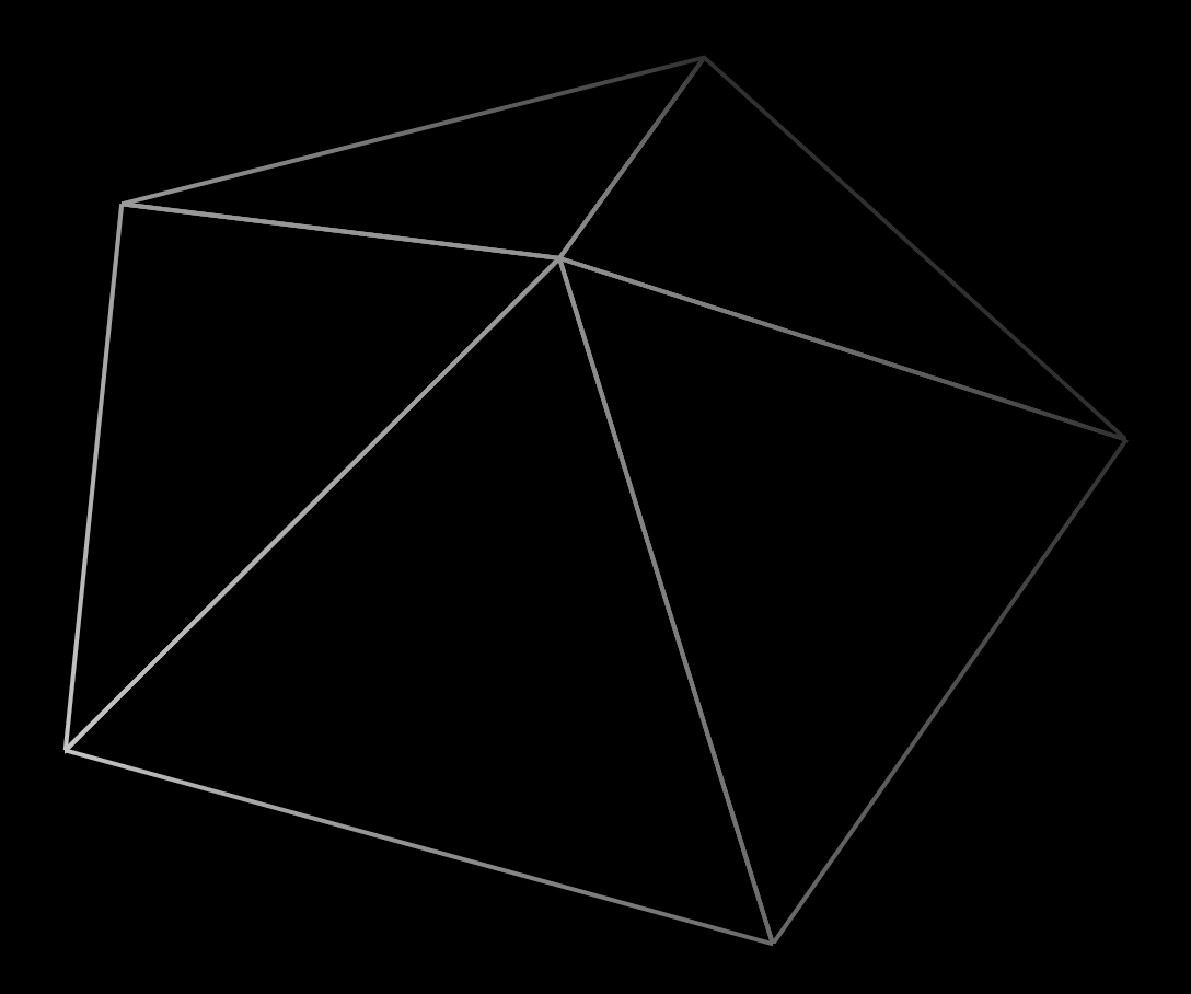
With this technique I was able to generate a much more efficient tessellation:
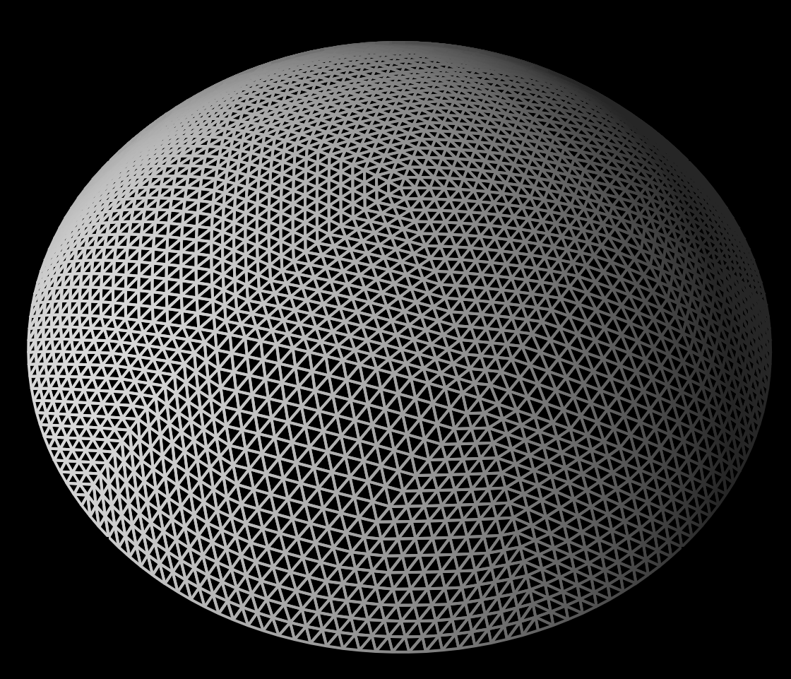
Tessellating The Bevel
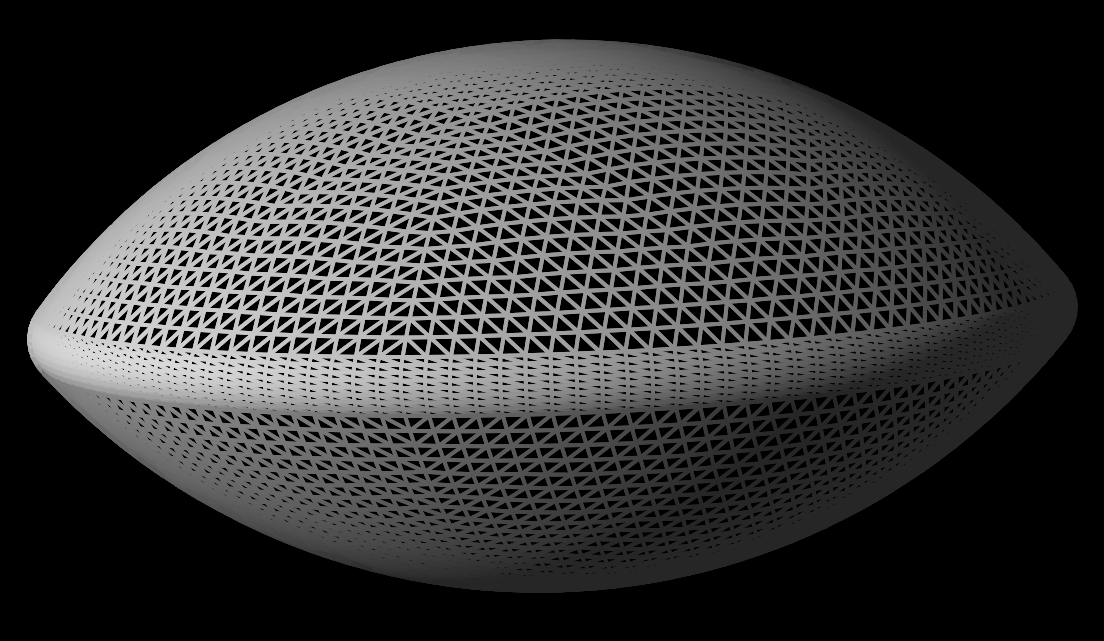
Now we need to tesselate the bevel. To do this I take the vertices which form the circle edge at the bottom of the top sphere surface and calculate the angle of each vertex about the y axis. I then use these angles to sweep around the torus ensuring that the torus vertices weld perfectly with the top and bottom sphere sections.
Vertex Welding
Due to how recursive subdivision works a lot of duplicate vertices are generated.
I’d rather not have the graphics card waste time transforming the same vertex over and over, so as I add vertices to the mesh I hash vertex positions into a 3D grid (~1mm cells) and reuse an existing vertex if the position and normals match within some small epsilon value.
With vertex welding the reduction in vertices is dramatic: 53000 to just 6500.
For more information on vertex welding please refer to the discussion in Real-Time Collision Detection by Christer Ericson.
NEXT ARTICLE: How The Go Stone Moves
Hello readers, I’m no longer posting new content on gafferongames.com